Without question, the rise of 5G has changed the landscape of wireless testing. One of the biggest changes is the ability of test engineers to perform over-the-air (OTA) testing without connecting anything or having a special setup. This is something that was not historically possible with past generations of wireless devices, as a result of FCC regulation and spectrum licensing law. OTA testing has the potential to revolutionize wireless device testing and enable innovative testing of advanced antenna systems (AAS) and antenna array technology.
However, there are several critical disadvantages of OTA testing that limit its applicability to all 5G sub-6 GHz (5G FR1) and millimeter-wave (5G FR2) device testing. One such consideration is the variability of OTA testing, which appears to be many times that of traditional coaxial transmission line test methods. Equally, there are limitations to coaxial test methods addressing the test needs of the latest beamforming and multi-input multi-output (MIMO) antenna technology. It is becoming increasingly clear moving forward that successful testing of 5G wireless technology must include OTA and RF over coax testing to tackle the pre-existing and emerging challenges of 5G device performance and conformance testing. What is most important is to understand the advantages and disadvantages of both to determine where and when to use each test approach.
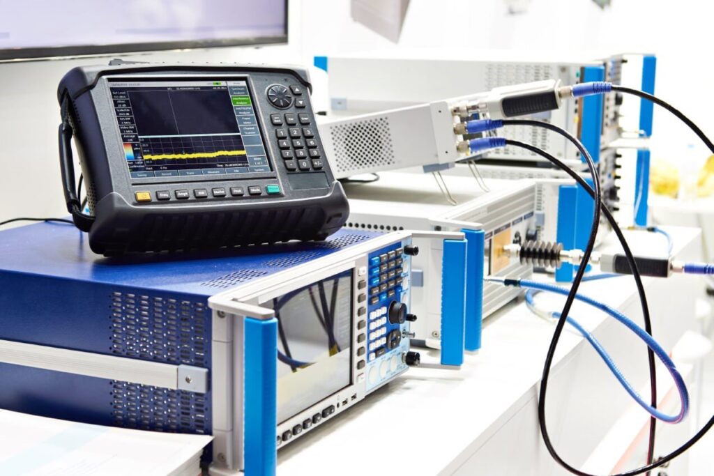
Figure 1. Successful testing of 5G wireless technology must include OTA and RF over coax testing to tackle the pre-existing and emerging challenges of 5G device performance and conformance testing. Source: Adobe/Sergey Ryzhov
5G OTA testing 101
A single AAS employing MIMO technology for 5G FR2 base stations (BSTs) may have as many as 128 antennas with 64 transmit and 64 receive (64T64R) antennas. These multi-user MIMO (MU-MIMO) systems are now generally being designed to also support three dimensional beamforming (3D beamforming). This means that a given device would require 128 connectors and cable assemblies in order to test the full capability of such an AAS. Other design considerations for 5G devices, especially handsets, internet of things (IoT) gateways and consumer premise equipment (CPE), is to fit a higher density of 3D beamforming and MIMO technology into even smaller packages. For handsets especially, these devices are also going to include a variety of antennas and radio hardware that support other telecommunications protocols, such as Wi-Fi (2.4 GHz, 5 GHz and even 60 GHz), Bluetooth and NFC.
5G hardware supporting advanced capabilities has substantial constraints on the footprint and cost of the RF boards. Supporting connectorized testing for such systems may at times be impractical due to board and connector size constraints and the increased cost and board size needed for coaxial test ports. There have been strides in developing extremely compact coaxial connector heads and surface/edge-mount coaxial connector ports, but these connectorized options may still require more board space than can be allotted given the extreme dimensional constraints for modern RF devices.
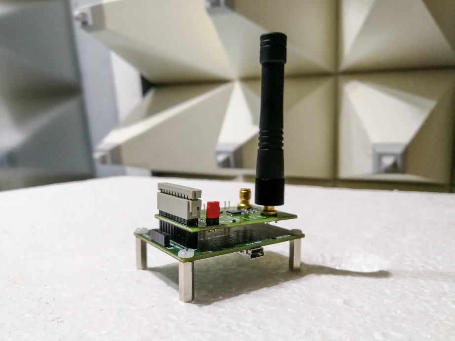
Figure 2. A physical interconnect is not necessary and many tests can be performed by placing a device in an anechoic (externally shielded and internally absorbent) chamber. Source: Adobe/Audrius MerfeldasHence, the industry organizations developing 5G standards are also incorporating OTA testing methodologies into the standards for 5G radios. With OTA testing, physical interconnect is not necessary and many tests can be performed by placing a device in an anechoic (externally shielded and internally absorbent) chamber. Given the lack of access to connectorized testing on some 5G devices, OTA testing will need to be able to test RF system performance and radio resource management parameters, dramatically increasing the amount of OTA testing compared to prior generations of cellular telecommunications. This includes electromagnetic compliance (EMC) testing, which is necessarily growing more complex to account for the new test cases introduced with the addition of new FR1 frequency bands and of the FR2 millimeter-wave spectrum.
Given the potentially infinite antenna system and radio configurations of 5G devices, OTA testing is a practical method of testing these diverse configurations without the need for custom fixturing or interconnect beyond the initial OTA chamber, antenna and test instrument setup. Moreover, beam characterization, check beam acquisition, beam-tracking performance and other OTA test methods are able to capture the real-world behavior of AAS in a very short amount of time. With a 5G OTA test system, a device may even be tested without first customizing the test to the device, as the 5G standards for OTA testing will ensure compatibility.
Primer on coaxial test methods for wireless devices
Coaxial connectorized testing of radio hardware has been the primary test method for performance and conformance testing throughout the cellular telecommunications device design and production phases. Coaxial testing enables extremely precise measurements that are highly controlled, repeatable and reliable. The quality of coaxial testing is partially due to the much lower loss and lower interference transmission medium of using coaxial transmission lines instead of an air-link. With a coaxial test system, the energy within even a complex multi-port device can accurately be measured at each port. This enables accurate characterization of the device’s behavior.
Moreover, coaxial test methods enable testing of individual sub-circuits, components or even individual devices within a complex radio system. Non-destructive coaxial testing can even be done using probes, solderable test connectors or test ports built into the RF board. Given that test signals are intrinsically shielded within a coaxial test system, externally shielding during testing is not usually required, and a very small test footprint can be achieved. For many test labs, real estate is at a premium, and there is a demand to minimize test station footprint.
With coaxial tests, there are a variety of RF accessories that can be used to extend and customize test stations beyond the original capability of the test instruments (typically a vector network analyzer (VNA), signal/spectrum analyzer (SA), power meter and signal generator). For instance, a two-port VNA in its original and economic configuration would normally only be able to test a two-port device; however, with the addition of an RF switch-matrix, power dividers/combiners, attenuator matrices and phase shifters, this device could be configured to test tens of ports in rapid succession. Such augmentation extends a mere two-port VNA to emulate the capability of a much larger and more expensive multi-port VNA.
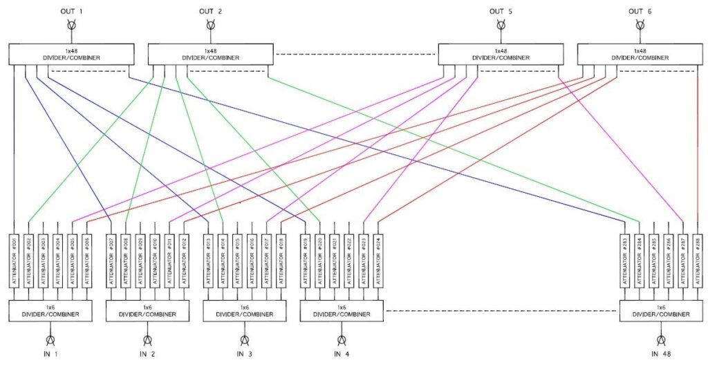
Figure 3. This is a bidirectional 48 x 6 handover test system with an attenuator on every RF path (288 total attenuators). Source: JFW Industries
In this way, multi-port VNAs can be further extended with hundreds of ports with comparatively minimal increases in cost and test complexity beyond configuring the primary test instrument. Moreover, coaxial test systems with port extensions or attenuators also generally include some sort of programmable remote-control interface (Ethernet, serial, parallel or USB). Scriptable command sets allow for elaborate test scenarios that would be very time consuming and expensive to recreate in a physical space.
OTA versus coax
While it is true that OTA testing can expose devices under test (DUTs) to certain scenarios that cannot be easily replicated when testing through coaxial cables and components, there are still some advantages to more established methods of testing with coaxial interconnect. When performing OTA testing, it is impossible to completely control the testing environment. The variability of test conditions, even within an anechoic chamber, can significantly impact the test results. Additionally, in some cases it may be difficult with OTA testing to precisely determine the cause of test failure or poor performance, and the troubleshooting process is likely to then involve some type of connectorized testing or probing.
In a coaxial test system, documented specifications and performance tolerances make test results more reliable and troubleshooting more scientific. With the use of coaxial interconnect components such as RF switches and power divider/combiners, hundreds of devices can be connected in a relatively small amount of space (compared to physically spacing devices apart within an anechoic chamber). Adding RF in-line attenuators to the mix increases this advantage by allowing for the simulation of signal loss over an extended distance, which is not typically feasible with OTA testing without physically increasing the dimensions of the test area or anechoic chamber.
There are also other 5G OTA testing issues still being tackled by the research community that are likely to result in the development of innovative test methods and technologies, such as with direct far field (DFF), indirect far field (IFF)/compact antenna test range (CATR), and near field to far field transform chamber testing. A variety of OTA methods exist, including hybrids of these methods, as there are drawbacks and benefits to each approach. For instance, DFF OTA testing is performed far enough from the device’s antenna array that the signal energy is in the square-law region and likely to not be reacting to nearby test apparatuses as would near-field OTA test systems. However, at these ranges the test signals can become extremely weak, and pose the additional challenge of being frequency dependent. Hence, for DFF testing, a device with both FR1 and FR2 capability may require multiple OTA test setups or active probing to achieve accurate measurement results for the various frequency bands. These issues generally do not exist with coaxial connectorized testing as long as the test equipment and interconnect is designed to accommodate the highest desirable frequency band.
For characterization testing, performance testing, conformance testing and for many types of troubleshooting coaxial connectorized testing will still be dominant over OTA for 5G, and future applications. An example of this is wafer-level yield testing extremely complex RF integrated circuits (RFIC) and monolithic microwave integrated circuits (MMICs). In a wafer testing environment, it would be extremely costly and take years of development to integrate OTA testing into the quality control process within a wafer fabrication facility (fab). Essentially, the test equipment used in wafer-level testing would require complete redesigns, which would require massive investment and more time than may be worthwhile given the investment made into the current machines. Additionally, an on-board antenna or probe with antenna fixtures would be needed for the on-wafer RF circuits to perform OTA testing. As physical contact testing is necessary for semiconductor wafer-level testing for DC and digital functional testing, adding 5G RF testing scenarios to the probe station testing program is likely less complex and costly than inventing new OTA test protocols for these devices.
Conclusion
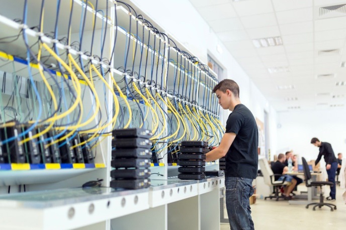
Figure 4. When reliability, repeatability and accuracy are the key testing parameters, coax testing remains the superior choice. Source: Adobe/NBADCREATIVITYThe advent of advanced antenna systems and the latest 5G frequency bands pushing into the millimeter-wave spectrum is creating unprecedented upheavals in telecommunication device performance and conformance testing. To meet these demands, 5G standards are including OTA test approaches that enable diverse testing capability previously inaccessible with traditional coaxial transmission line-based testing. However, OTA testing presents several key limitations that coaxial testing does not exhibit. Where reliability, repeatability and accuracy are concerned, coaxial testing will likely continue to dominate over OTA testing. However, when flexibility, speed and testing diverse antenna configurations are the primary objectives, new methods of OTA testing bring much to the table.
For more information on coaxial testing and attenuators, visit the JFW website.